With a few simple modifications, you can convert your standard GBA SP from a regular, front-lit AGS-001 to a Backlit AGS-101. Also, a benefit of the modification is the backlit screen is actually slightly brighter than a stock AGS-101.
You will not be able to use an existing front-lit screen, you will have to pick up an AGS-101 screen from either a donor console or from eBay or Amazon.
So, how do you modify a Game Boy Advance SP to have a backlit screen? To modify your AGS 001 to a backlit AGS 101 we need to cut a trace on the motherboard and connect a 12v regulator.
How to Convert GBA SP AGS-001 to AGS-101

Accessing the motherboard
Accessing the motherboard on a Game Boy Advance SP is quite easy. To gain access, you will need a Tri-wing screwdriver and a Philips head screwdriver.
I’ve actually written a more in-depth guide into reshelling the GBA SP for those who are interested where I got a little more into detail about the disassembly.
With the GBA SP sticker side up, use your Philips head screwdriver to remove the battery compartment and set it aside along with the battery itself (The battery just lifts up). Next, we will need to remove the 6 x Tri-wing screws around the edge of the console. One of the screws is slightly hidden in the battery compartment. Keep a note of where all the screws come from as two of them are slightly shorter then the other 4.


With the screws all out, we can now lift off the back of the housing and set aside. At this point, you may dislodge the volume slider or power switch, if you do set them aside and you can reattach before putting the housing back together.
With the motherboard exposed, we will be removing the 3 x Philips head screws holding down the board.
Please note, If your motherboard is a type C/AGS-CPU-01 like my original below then this mod cannot be performed! (Well, not easily at least for reasons I will get on to shortly!). Luckily, I have a lot of spares and all other motherboards do work. CPU-10 & CPU-11 seem the most common. With this, I switched to my AGS-CPU-10 board.


Gently lifting up the motherboard will expose the ribbon cable. We need to pull down on the brown tabs either side of the brown ribbon cable keeping it locked into place. This will allow us to remove the cable and free the motherboard.


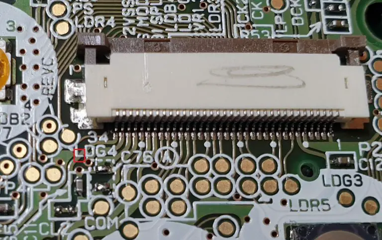
With the motherboard free, we can now find the 1st area we need to modify. We need to cut the trace from the 1st pin of the display connector. This is the reason we cannot use the CPU-01 boards as the trace is actually underneath the connector.
Use a craft knife to cut the trace as pictured below.


This is our voltage regulator. I’ve opted to use the Pololu 12V Step-Up voltage regulator as this is the smallest I have found and very inexpensive.
We will be connecting the wires from the motherboard to the regulator.

The first wire we need to solder is from the 1st pin of the display connector. Fix the wire to pin one and feed the wire through the hole on the motherboard near VR23 and flip over the board as pictured below.


Next, we will be solder a wire to the pad just above the CPU as pictured below. Make sure not to bridge any of the pins of the CPU.


*Be careful when soldering your wire, especially above the CPU. It would be very easy to accidentally slip & remove some of the surface mounted components like the capacitor at C54*

Locate C1 on the power switch and solder a wire to it. make sure the wire has enough length to reach across the board.

With the wiring to the motherboard finished we will now move onto soldering the voltage regulator in place.

The 1st wire from the display pin will be soldered to VOUT
The 2nd wire from the pad above the CPU will be soldered to GND
Lastly, the 3rd wire from C1 will be soldered to VIN
Once connected, I recommend wrapping the regulator in some electrical tape to stop anything shorting when everything is reassembled.


Now we should be ready! Only one last thing, In order for the regulator to fit a small modification, is needed to the inside of the shell.
I’ve picked up a rather nice transparent black shell for my converted unit. Remove the piece of the shell using cutters or pliers. This allows the regulator to sit comfortably behind the volume slider.
We can now install AGS 101 screen into the new shell and put everything back together.

The Results
With the modification complete and an AGS-101 screen installed we can see the difference. Colours are vibrant and you’ve just saved yourself a bit of money and time not having to track down an original backlit Game Boy Advance SP.

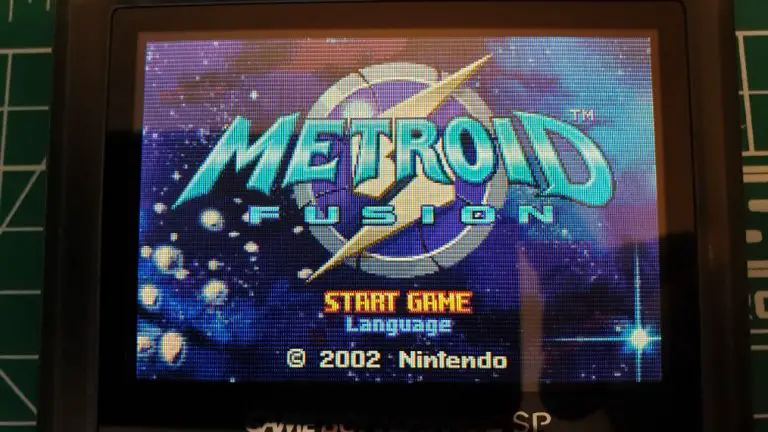
Below is a comparision of a frontlit Game Boy Advance SP vs the modified AGS-001 with backlight fitted.


As you can see, our converted SP is as bright as the Game Boy Micro’s backlit screen and actually slightly brighter than a stock AGS-101.
Conclusion
Converting an AGS-001 to an AGS-101 is quite easy and a fun project. The process is a lot cheaper than spending the cash to buy a stock AGS-101. The benefit of having a rechargeable battery is also very nice.
I hope this helps! If you prefer the original form factor of the original Game Boy Advance check out my guide on Installing a backlit AGS-101 mod into the original GBA.
*These AGS-101 screens are getting much harder to find and also much more expensive. If you are having trouble finding one I would recommend picking up an IPS screen, they are brighter and use less power. The IPS screens are easy to install, come with a pre-modded shell and require no soldering. Full installation guide to here.*